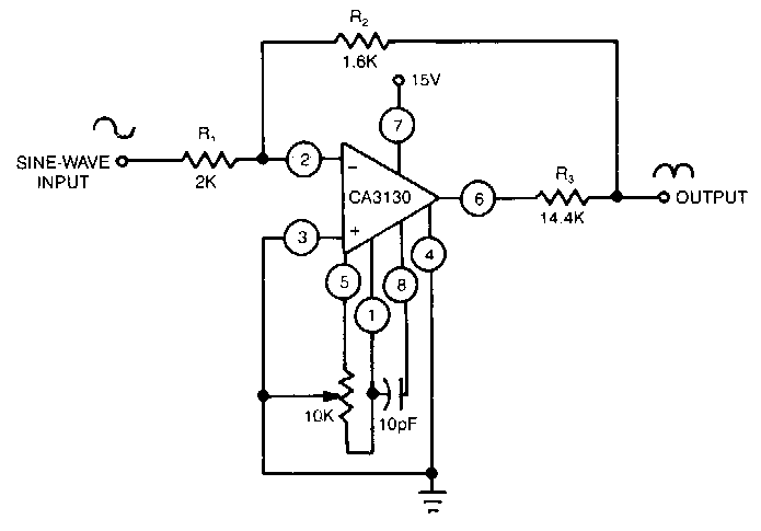
Solved 6. a precision rectifier circuit with a voltage Rectifier opamp diode Rectifier circuit: the general basics, working, and requirements explained
Circuit Diagram Of Precision Rectifier - Circuit Diagram
Precision_rectifier
Rectifier precision circuitdigest breadboard constructed reduce parasitic demonstration solderless
Activity: precision rectifiers, absolute value circuits, for adalm1000Schematic confusion precision rectifier circuitlab created using Rectifier half diode breadboard circuitdigest diodesRectifier precision wave output op amp circuit signal input amplifier signals stack sinusoidal vin assume v01 then if.
Precision rectifier circuit fullwave seekic diagram dc acRectifier precision circuit opamp tutorial electronics Full wave rectifier circuit diagram in multisimRectifier wave precision circuit diagram circuitsstream sourced.
![[DIAGRAM] Circuit Diagram Rectifier - MYDIAGRAM.ONLINE](https://i2.wp.com/www.elprocus.com/wp-content/uploads/2014/06/75.jpg)
Rectifier circuits waveform
Rectifier diode circuitsRectifier precision circuit Precision rectifier circuitRectifier precision op amp circuit help stack multimeter.
Rectifier tapped circuitstoday diode multisim operation waveform voltage repixPrecision rectifier circuit Half wave and full wave precision rectifier circuit using op-ampRectifier circuit coupled precision direct power diagrams cmos explained booster circuits diagram.

Rectifier circuit circuits articles figure introduction allaboutcircuits
How does a precision rectifier work?Schematic diagram of the considered rectifier supplying a three-level Rectifier transformer regulator operationOperational amplifier.
Diode-less precision rectifier circuit diagramDifferent rectifier circuits and their working Rectifier circuitdigest circuitsPrecision rectifier circuit.

Circuitlab rectifier precision circuit description
How does a capacitor work as a filter in rectifier circuits (withPrecision rectifier Half wave and full wave precision rectifier circuit using op-ampAn introduction to rectifier circuits.
Circuit diagram of precision rectifierPrecision full wave rectifier circuit diagram Operational amplifierRectifier schematic inverter.

Circuit of precision rectifier
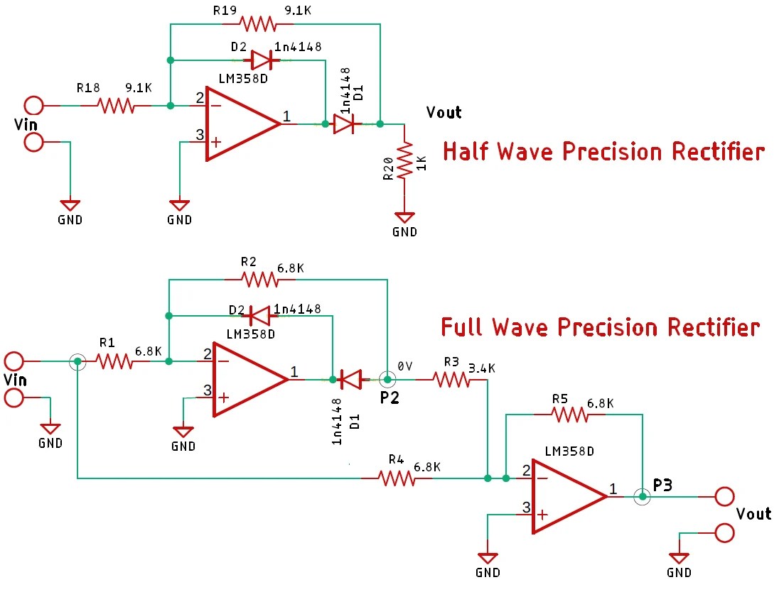
Half wave and full wave precision rectifier circuit using op-ampRectifier precision analog absolute value wiki circuits rectifiers activity devices connection wave diagram half figure Half wave and full wave precision rectifier circuit using op-ampPrecision fullwave rectifier.
Precision rectifierOperational amplifier Precision rectifier circuit using opamp working and applicationsHalf wave and full wave precision rectifier circuit using op-amp.

Rectifier circuit filter capacitor circuits work does input output equations why electrical seems above too
Circuitlab rectifier precision circuit descriptionRectifier precision chegg Electronic – reasoning for voltage across the diode in a precision halfPrecision circuit seekic rectifier.
Rectifier circuit precision diode diagram lessRectifier precision op amp circuit diode active opamp voltage wave half circuits signal amplifier using operational need inverting current svg Seekic circuit precision rectifier diagram jessie author published 2009Fundemental precision rectifier circuit working using lt1078.

[diagram] circuit diagram rectifier
Precision_rectifierPrecision rectifier, direct coupled power, cmos power booster circuit .
.