Adder decimal binary circuitverse coded Full adder circuit: theory, truth table & construction Adder in digital electronics, half adder and full adder in digital
How to Design Half Adder and Full Adder Circuits? - EE-Vibes
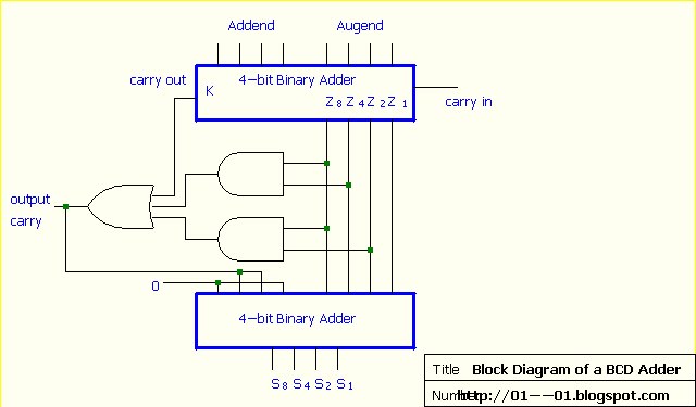
Digital electronics: binary coded decimal (bcd) adder
Combinational circuit
What is adder?Adder circuits adders technobyte Adder circuitverse13+ full adder block diagram.
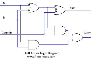
Full adder using two half addersBinary decimal encoder deskripsi Adder circuit binary logic output xor boolean electronics diagrams derivedFull adder circuit diagram.
Logic diagram
What is meant by arithmetic circuits?Circuit diagram of proposed full adder Bcd decimal adder circuit binary javatpointFull adder circuit diagram.
Adder bcd decimal binary coded digital electronics stage parallel carry digits output nextHow to design half adder and full adder circuits? Binary adder circuit / circuit additionneur binaireCircuit design decimal adder.

Logic diagram binary decimal circuit bit encoder gates two
Adder logic truth gates projectiot123 half sumWhat is the circuit's logic diagram of a (2-bit binary to decimal Adder circuit combinational half logicAdder in digital electronics, half adder and full adder in digital.
Block diagram of full adder circuitAdder decimal bit bcd binary coded Adder logic half implementationCommon adder circuit diagram.

4bit adder to decimal display
Adder truth logicAdder decimal circuits 4bit components Circuit diagram of decimal adderElectrical – 4ِ-bit adder in multisim – valuable tech notes.
What is adder?Circuit diagram adder common seekic Bcd adder giving strange output? : r/engineeringstudentsAdder circuit construction binary circuits qiskit sourav gupta.

Decimal to bcd circuit diagram
Adder electronicsFull adder in digital electronics Full adder circuit diagram and truth tableDecimal or bcd adder.
Adder additionneur binaire zpag electroniques gate sumAdder half circuit diagram svg following fig Introduction to full adderAdder circuit.
Adder circuits arithmetic logic diagram meant circuit given below
Binary coded decimal adder (4 bit)Adder bcd strange output giving electronics wrong sure did Adder circuit electronics outputs.
.