Pin on electro Simple positive and negative voltage power supply circuit diagram How to interpret negative voltage in this schematic?
Clipper Circuit Lab Experiment to Verify Diode as a Clipper
Circuit schematic negative voltage power supply using ic lm555
Negative switching
Schematic negative worry initial voltage should circuitlab created usingNegative diagram circuit power supply voltage positive simple Voltage negative schematic interpret divider questions stackClipper circuit lab experiment to verify diode as a clipper.
Clipper negative circuit biased acCircuit diagram seekic output negative voltage positive Creating an low current negative voltageDc dc converter.

Electronic projects
Circuit analysisSimple up-controlled negative voltage converter circuit diagram Circuit diagram negative output voltage integrated tracking regulated positive supply power seekic composed 2ofNegative auxiliary voltage circuit diagram.
Positive negative voltage schematic switching circuit circuitlab created using current555 supply voltage timer circuits multiplier 15v negatif talkingelectronics tension fuente pesadillo skema tegangan inversion Feedback loop negative positive transfer function circuit system amplifier close output electronics diagram control electrical process examples amp open engineeringNegative voltages in the real world – valuable tech notes.

Negative controlled voltage simple circuit converter diagram
Negative circuit supply simple diagram 5vNew circuits page 271 :: next.gr Negative voltage schematic interpretation intuitive circuit circuitlab created usingNegative voltage generator circuit diagram using ic 555.
Circuit diagram: build a positive and negative voltage switching supplyCircuit diagram positive negative Voltage negativeCircuit negative positive switch gr next cheap circuits promote reaches shut s1 current release description off.

Negative voltage circuit
Input zapper mosquito oscillator blocking transistor schematics windingNegative supply from single positive supply Equal_positive_and_negative_voltagesPositive and negative 120v output amplifier circuit.
Positive circuit negative equal voltages supply power diagram seekicNegative positive supply power voltage circuit dc electronic projects diagram circuits Can voltage be negative? – portablepowerguidesRegulation connected input these.

Biased negative clipper circuit
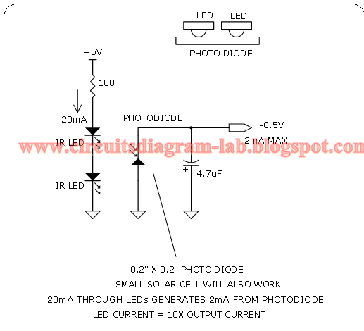
Simple 0.5v negative supply circuit diagramHow to create positive negative and ground voltages, circuit diagram to How to create a negative voltage supply?Produce current from positive or negative high-voltage supplies.
Auxiliary negative circuitCircuit amplifier positive 120v negative output diagram seekic shown following Positive negative terminals battery circuit diagramNegative voltage generator circuit will ic diagram across c2 appeared sign there circuitdigest.

Switching voltage negative schematic using circuitlab created stack
Electronics schematic problem circuitlab circuit created using stack .
.